
Skip to content

V1 took
37 versions.

We went through 37 versions to build V1. Most of that work came down to designing, printing and testing different versions: making it thinner, keeping water out and designing for strength.
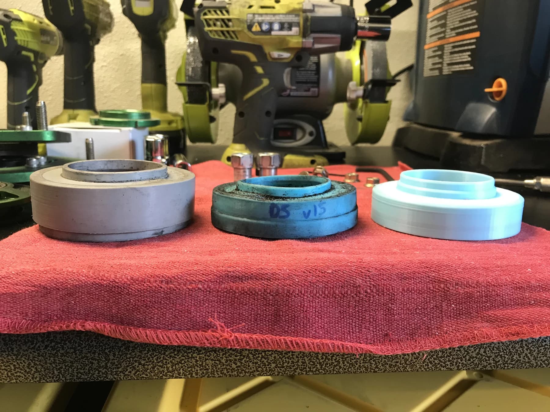
Three housing assemblies side by side on a red towel on the workbench.

Design. Print. Test. Repeat.

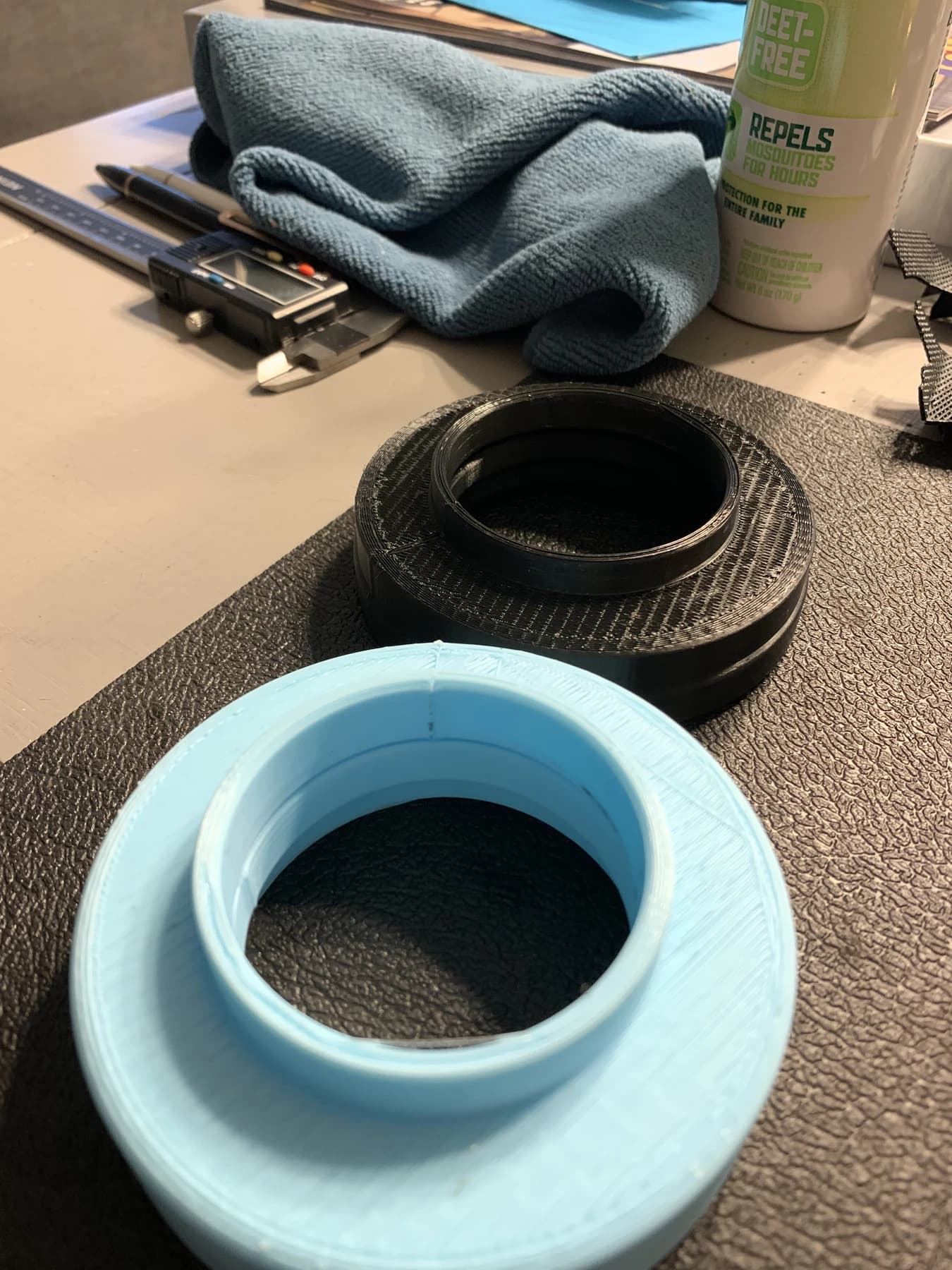
V1 took 37 versions to get right. We'd draw up a housing, print it, put it together and try it on a coilover. Then we'd change what wasn't working and print another one. These are some of the parts from that process.
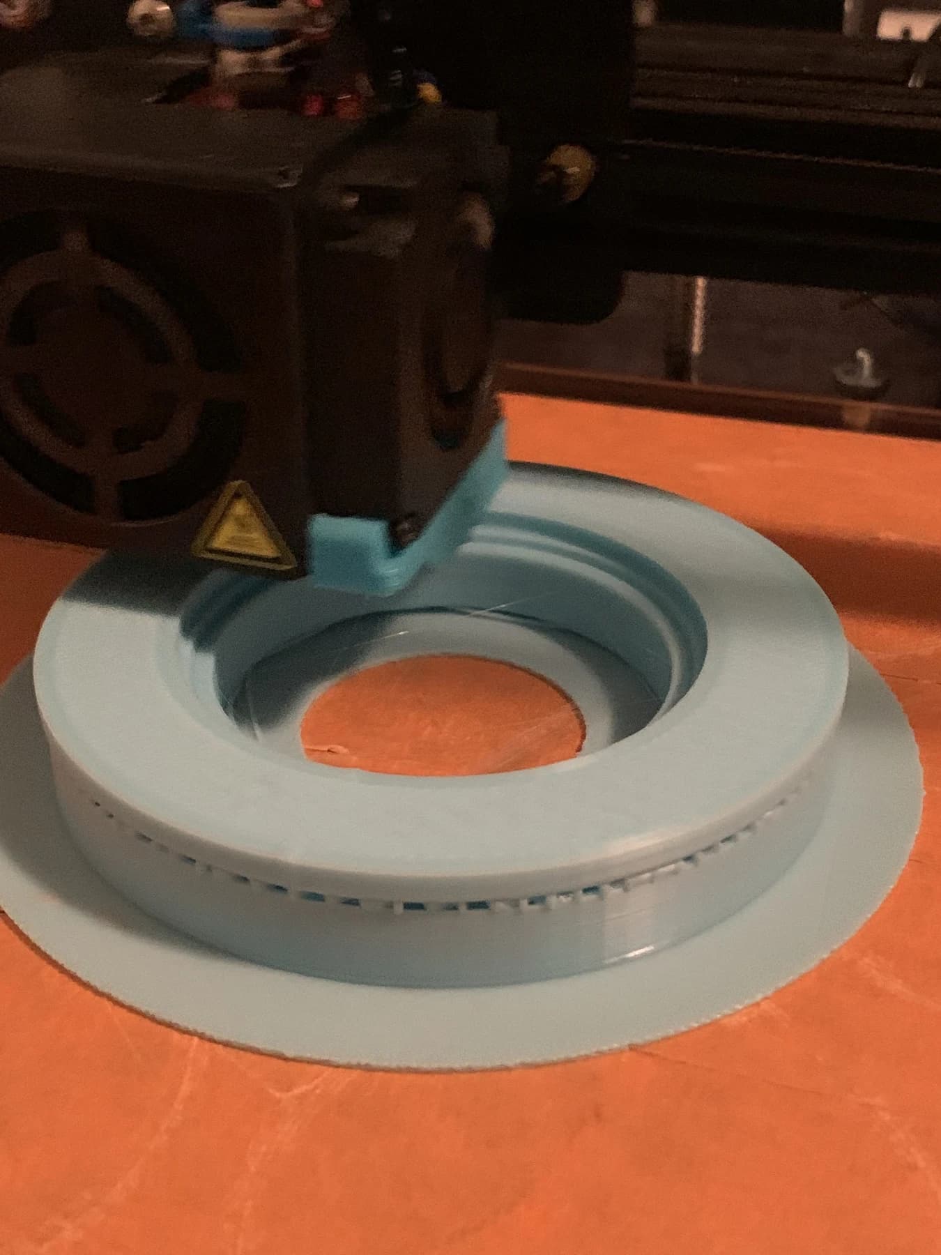
A pale blue housing on the bed of a desktop 3D printer.
Pale blue and black housing shapes side by side on a bench.
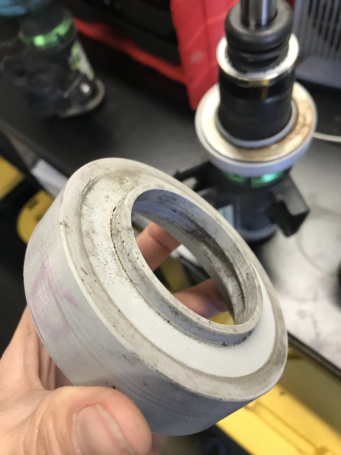
A pale printed housing held beside a disassembled coilover on the workbench.
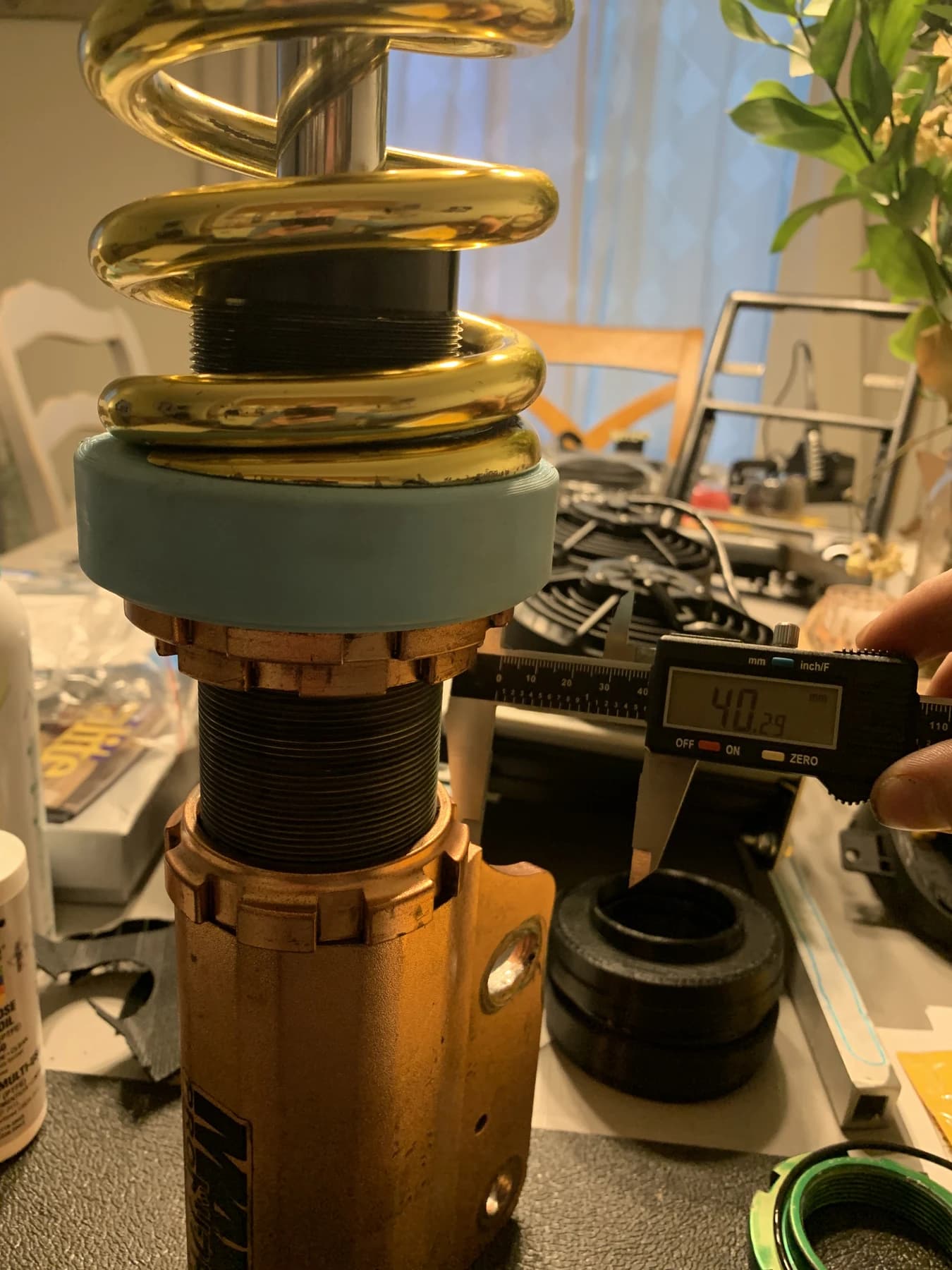
A pale blue housing below a gold spring with a caliper beside the lower perch.

Making it thinner.

Every bit of height under the spring matters when you're trying to get the car lower. We worked to fit the bearing, washers and seals into a thinner housing so the adapter would take up less room and allow a lower ride height. V2 will be even thinner.
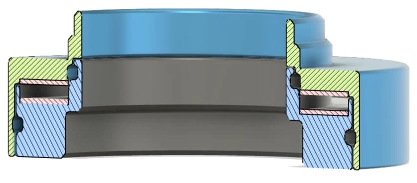
Section drawing of the V1 housing, bearing and seals.
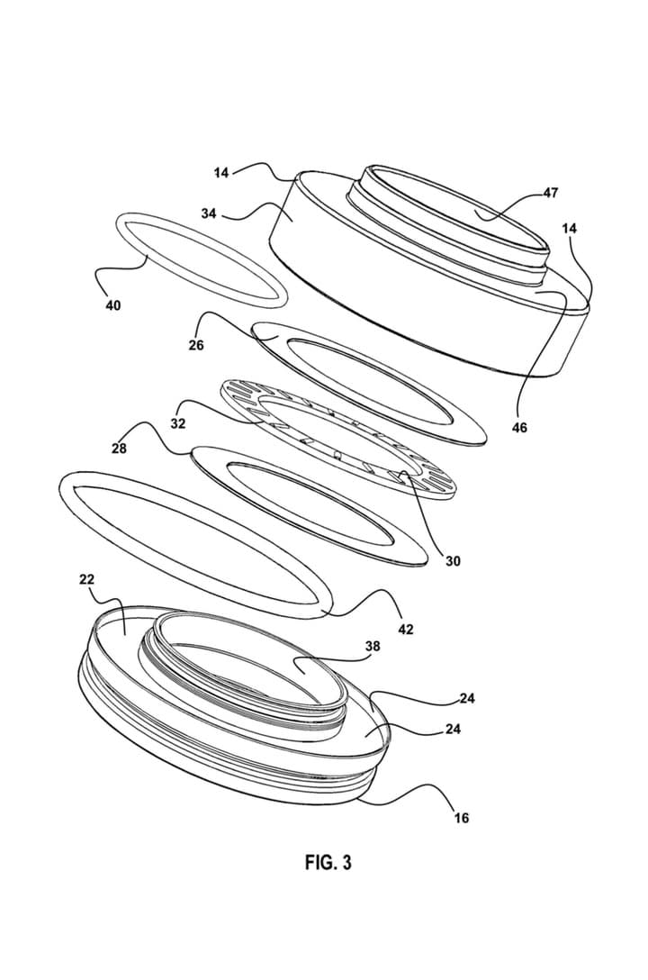
V1 exploded drawing with numbered parts: housing halves, washers, needle bearing and o-rings.
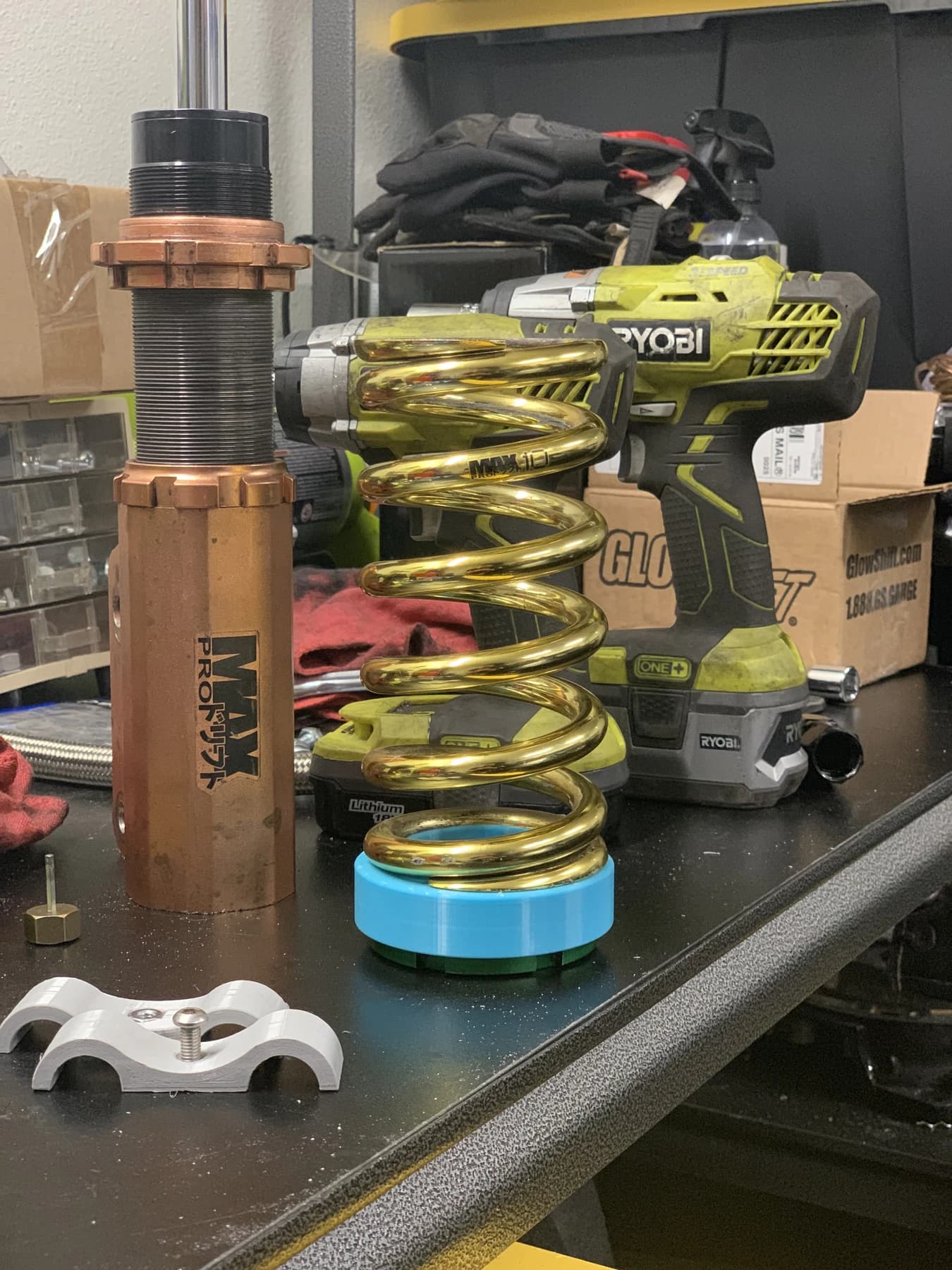
A gold spring with a blue adapter beside a disassembled coilover on the bench.

Keeping water out.

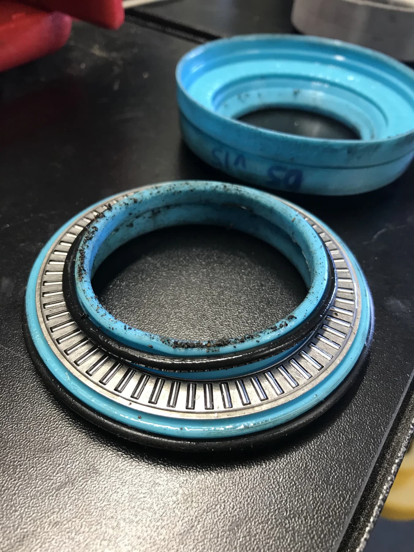
We made the housing and seal fit tight to keep water out. It's tight enough that we have to press the trapped air out of the bearings as we assemble them.
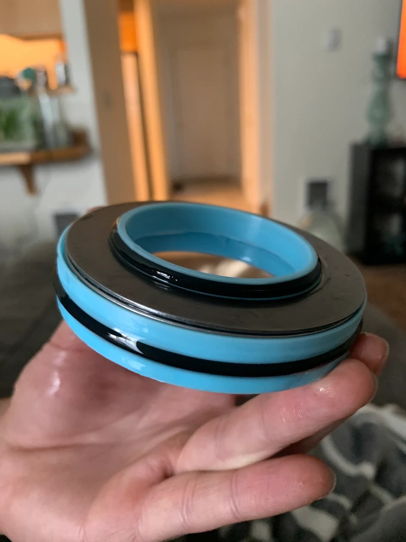
Blue housing held in a hand with a black seal around its upper edge.
An opened blue housing showing the roller bearing and surrounding surfaces.

Designing for strength.

Strength mattered throughout those revisions. The adapter sits under the coilover spring, so reducing its size was only part of the job. These photos show the housings and assembled coilovers from development.
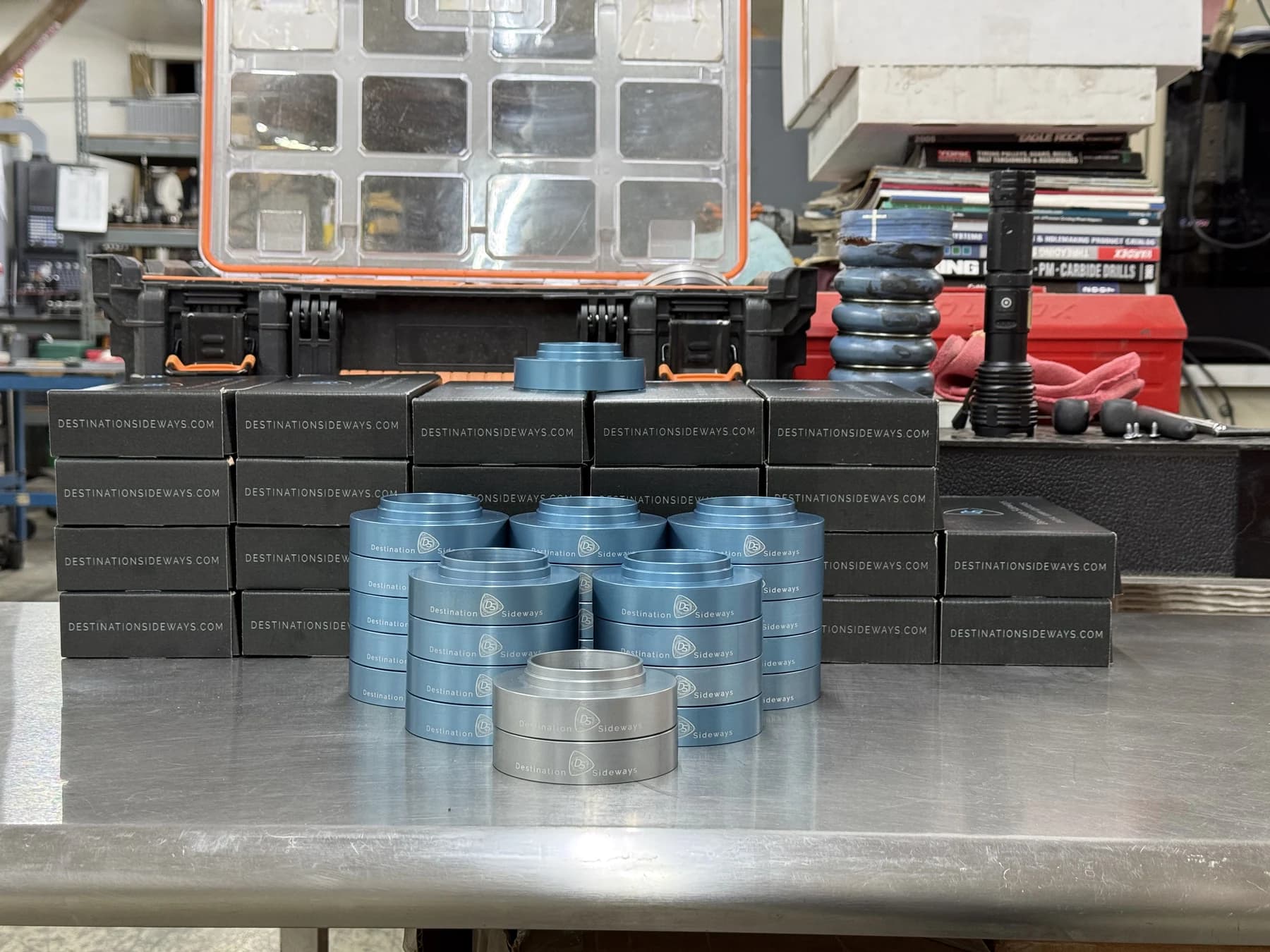
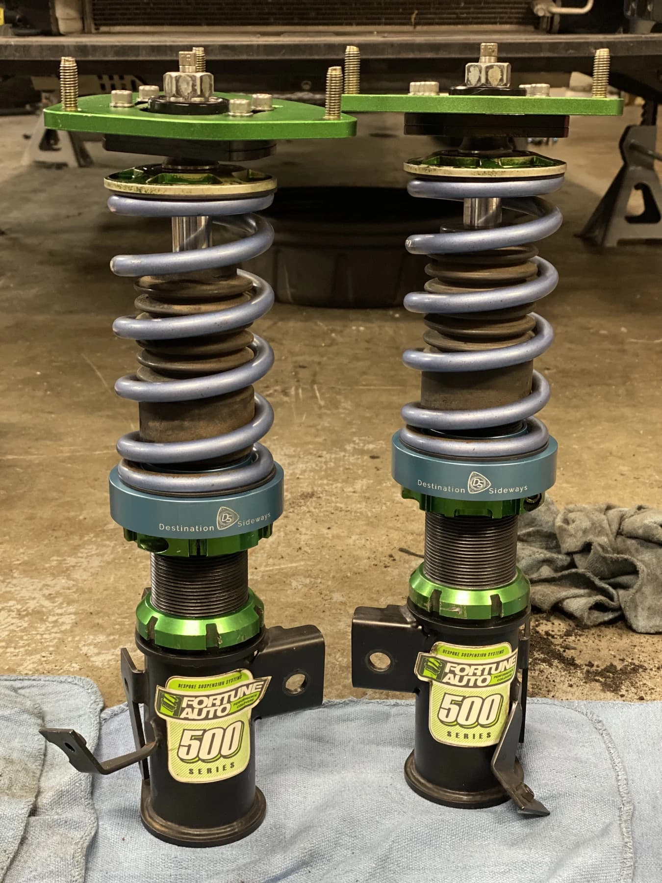
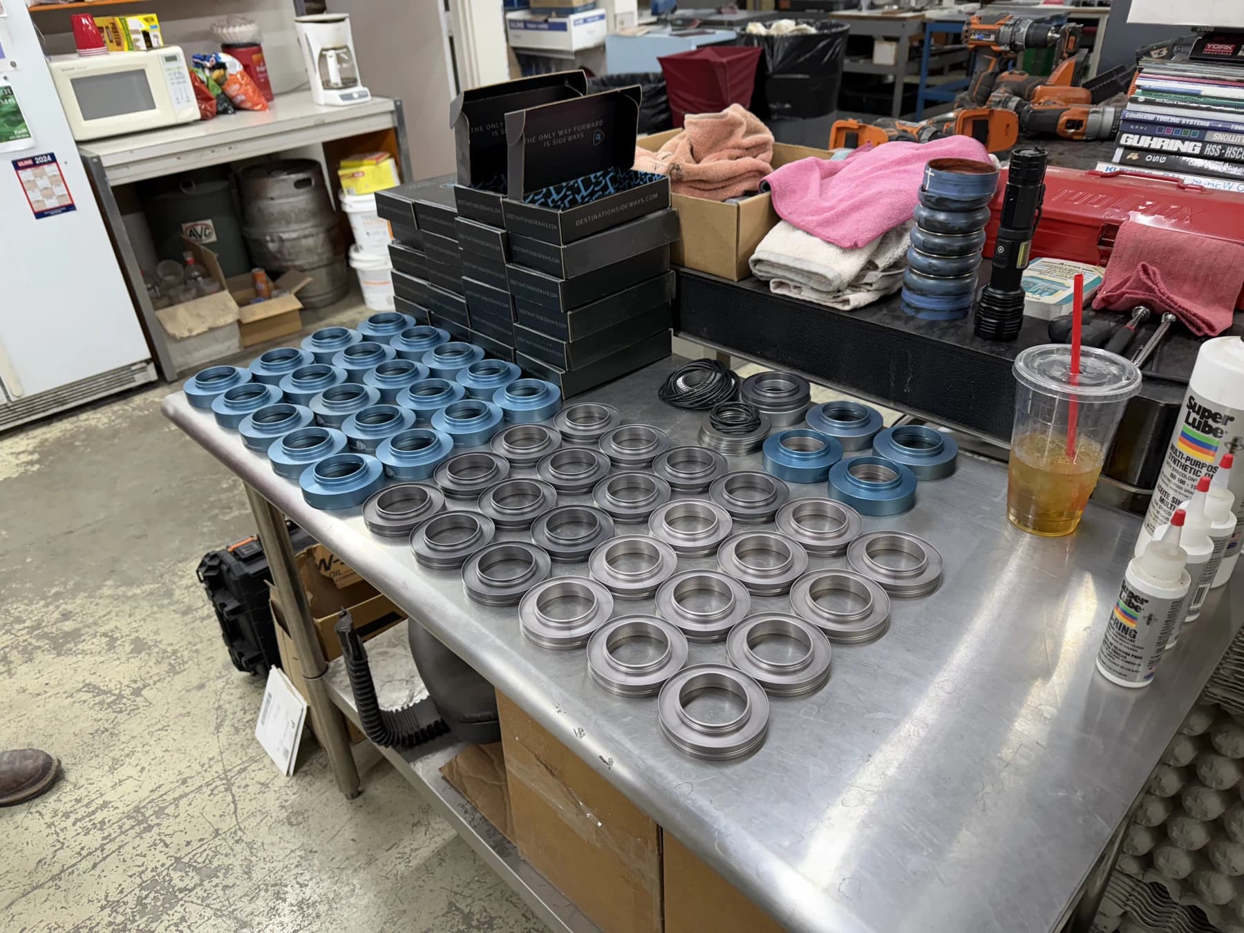
Stacks of blue and silver housings on a workbench in front of black boxes.
Two coilovers with blue adapters beneath their grey springs on a workbench.
Blue and silver housings with black seals laid out on a workbench.

Installed on the car.

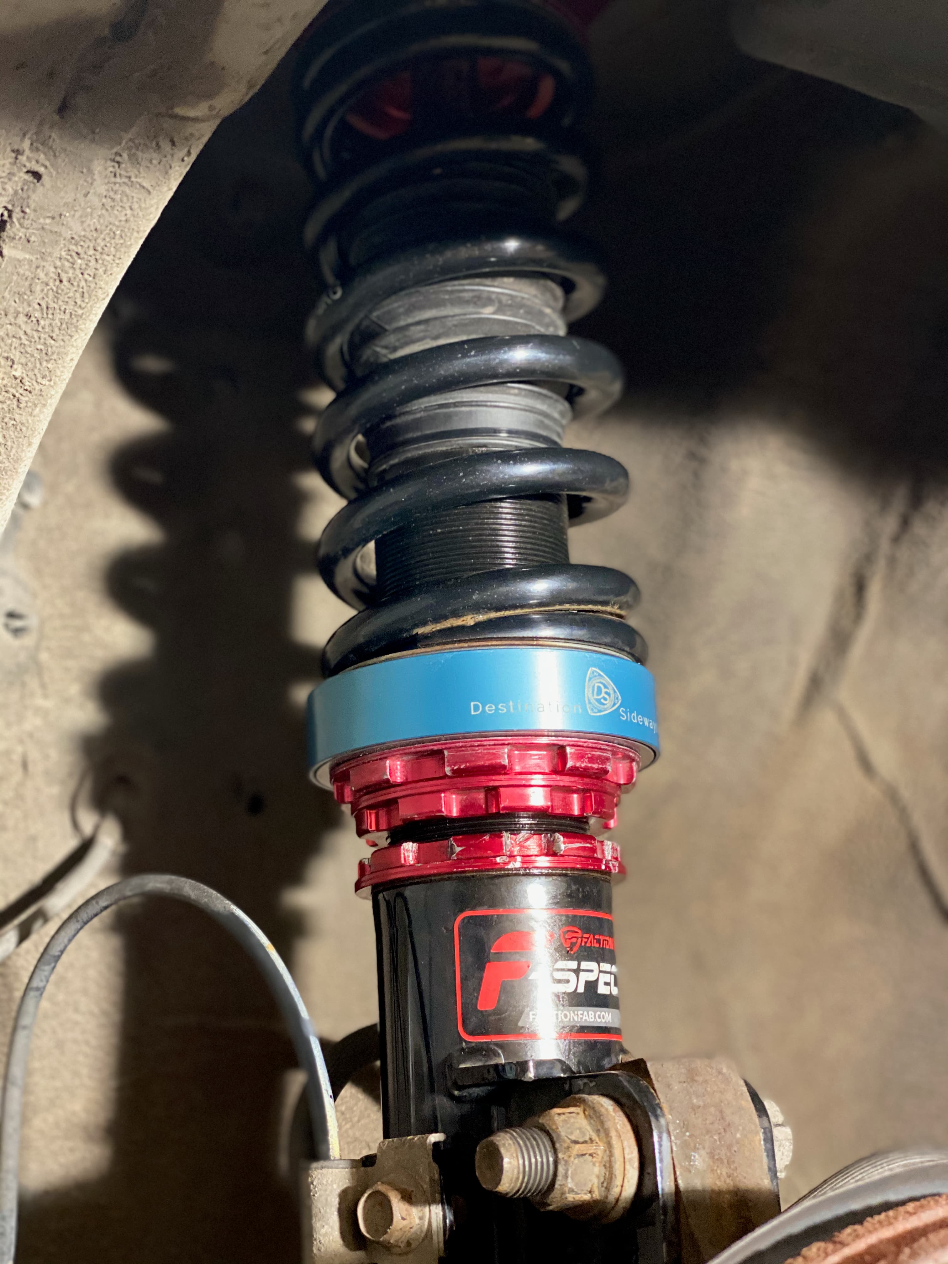
Close view of a V1 adapter installed between a black spring and the red lower perch of a coilover.
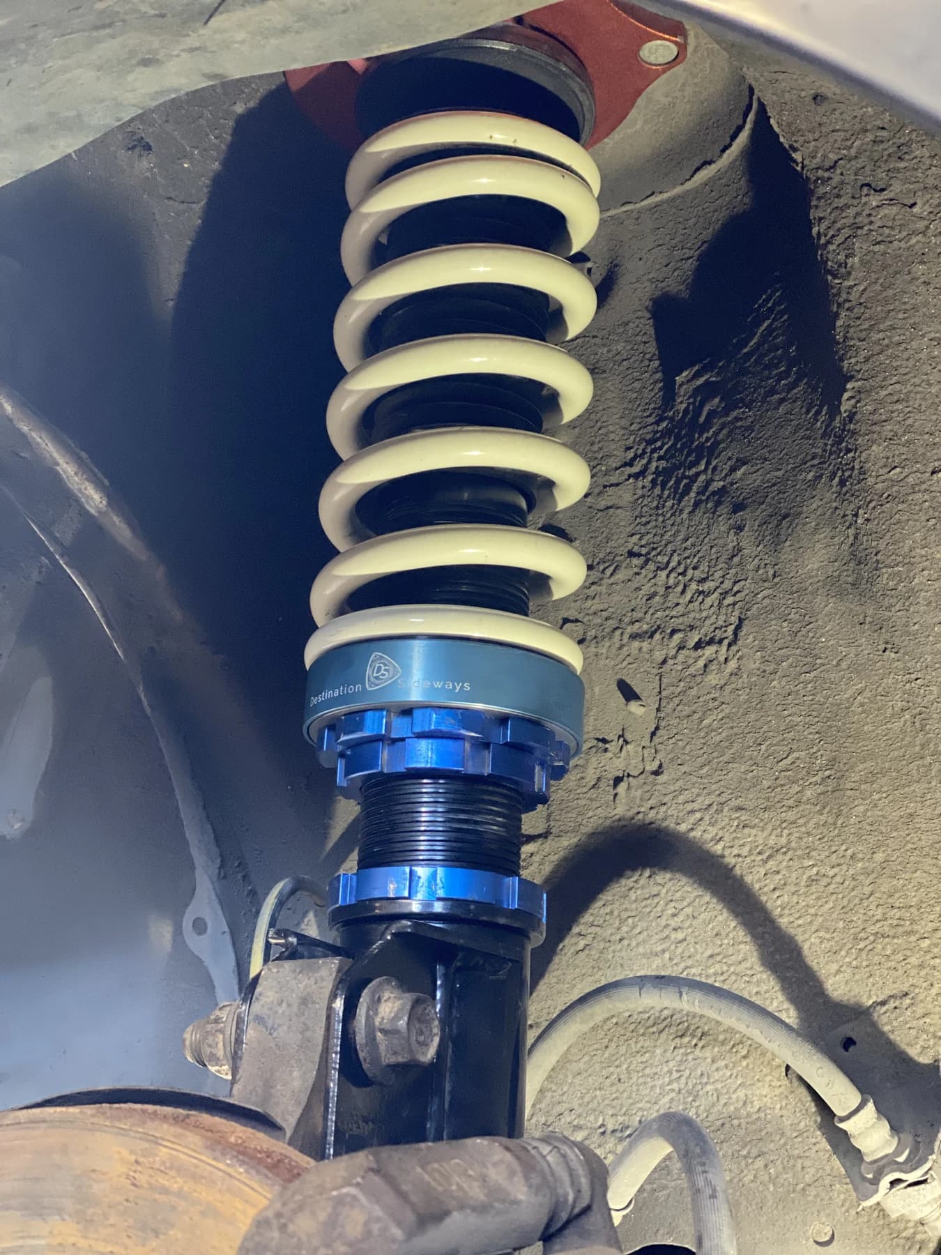
A blue adapter below a white spring on a coilover installed in a wheel well.
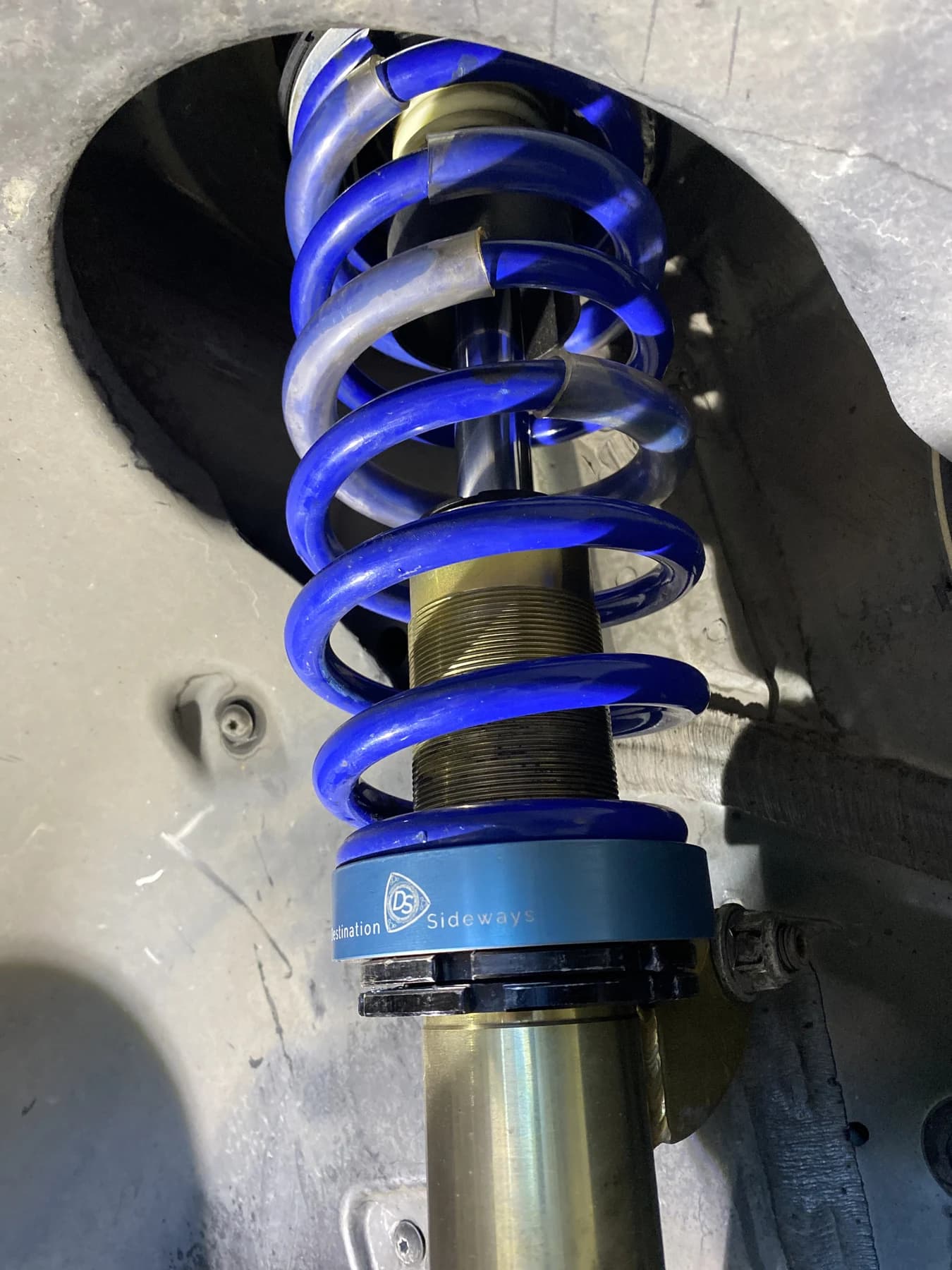
Blue V1 adapter below a blue spring above the black lower perch, installed inside a wheel well.
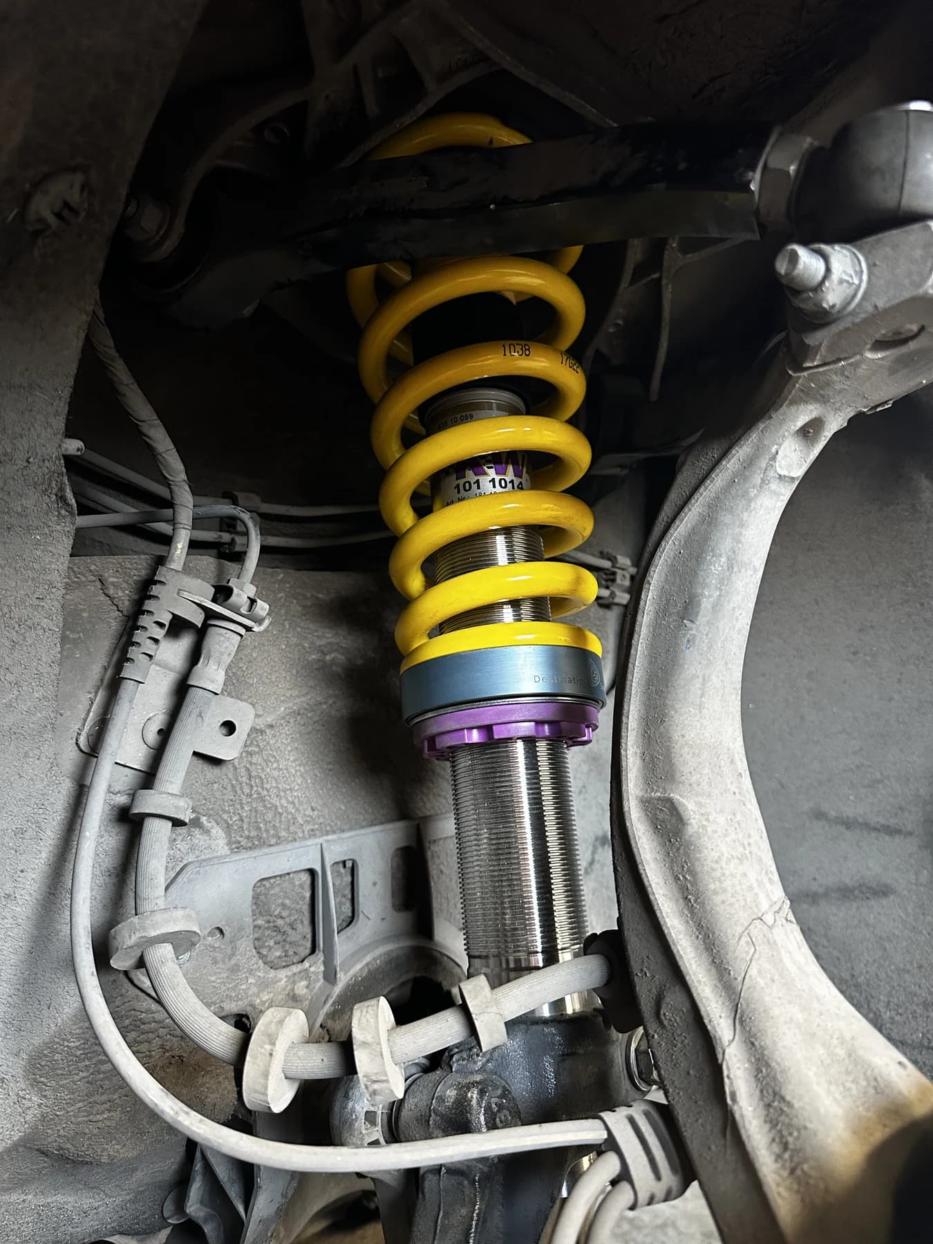
A coilover installed inside a wheel well, with a blue V1 adapter between a yellow spring and purple lower perch.

Some coilovers may need collar modifications.

Collar lip clearance, illustratedSection view. The bearing opening in the V1 adapter is narrower than the raised lip on the spring perch collar, so the adapter stops on top of the lip. The outside diameter of the lip is ground down, and the adapter then seats over the lip onto the collar. Illustration only, not to scale.
Illustration only. Not to scale.

Certain coilover versions may need a modification to the lower spring perch collar for V1 to fit. In the example below, the raised collar lip was too wide to fit inside the bearing.

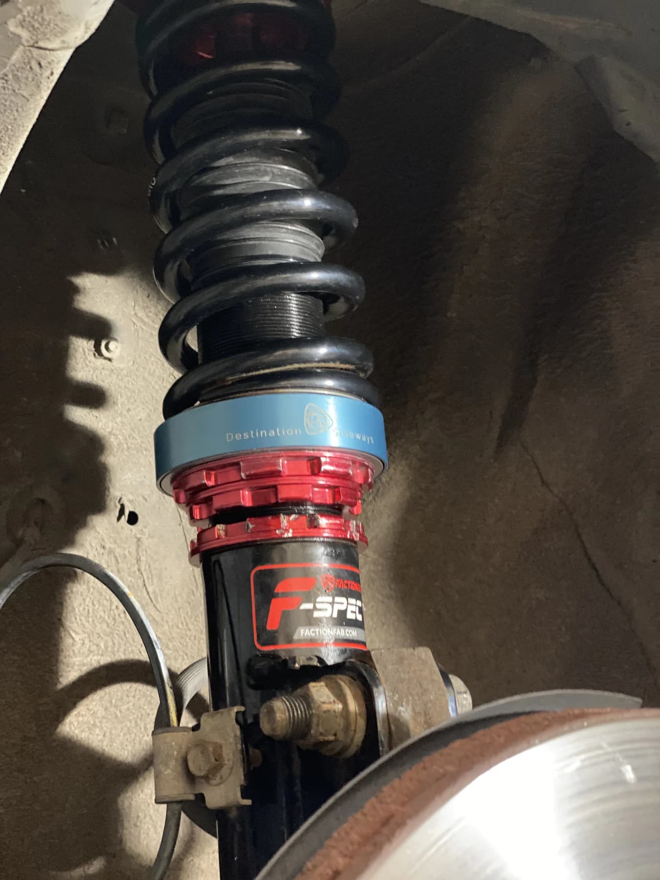
We ground the outside edge of that raised circular lip to reduce its outside diameter, giving the bearing clearance around the lip. The second photo shows the adapter installed afterward.

Confirmed fitments
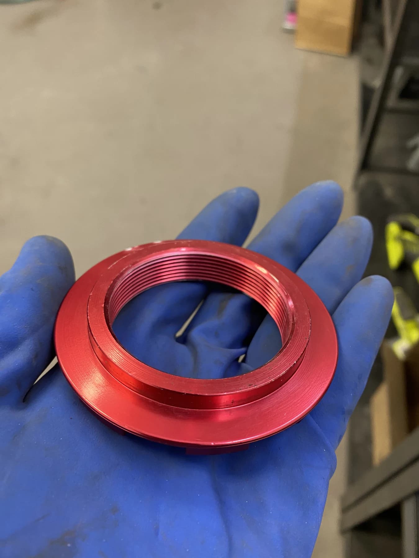
Red spring perch collar held in a gloved hand, showing the raised circular lip whose outside diameter was ground for this V1 installation.
Blue V1 adapter installed beneath a black spring above the red collar after the collar lip modification.

Making V1.

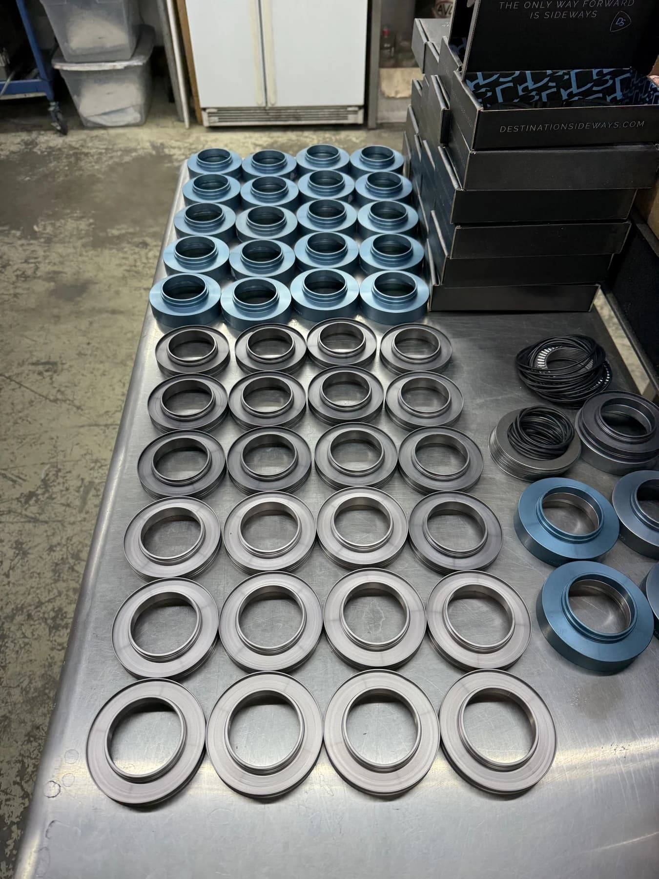
Those 37 versions led to the original V1 production run. Here are the housings and seals laid out for assembly. You can see the finished adapter's layout and dimensions on the tech page.